A Novice's Quick Guide To Avionics
©
2013 by Richard Harris
Rev.2A, Jan. 16, 2014
"Avionics" (the trade jargon for "aviation electronics") are the radios and related electronic gadgets that make it possible for a pilot to communicate with the ground (or other aircraft aloft), and to successfully navigate an airplane -- or have it fly itself -- from one place to another, while providing the pilot with electronic information about the ground over which he's flying, and the about the condition of his aircraft and its environment.
HERE'S A QUICK HISTORY & GLOSSARY...
(not comprehensive, but covering most major types in wide civilian use;
illustrated
version coming soon):
Part I: TRADITIONAL AVIONICS:
AVIONICS TECHNOLOGY
Like the rest of the electronics world, avionics has undergone a string of basic technology changes --
RADIO
COMMUNICATIONS Originally, in
the very early days (World War I), aircraft radios were simple "aerial
telegraphs," allowing the pilot or other crewman to communicate with the
ground by sending a stream of beeps -- "dots" and "dashes"
in "Morse code" -- to the person monitoring a ground receiver.
Eventually the aircraft radio worked both ways. By the late 1920s, two-way voice communications ("radio-telephone")
became common for military and commercial aircraft.
Pilots listed to the radio by speaker or (preferably) headphones, and transmitted voice through a hand-held microphone connected to the radio transmitter. The radio receiver was a simple AM-type analog-dial radio, while the transmitter was typically tuned by a complex of tuning coils, sometimes an array of them fixed at specific frequencies, which were selected by a rotaing switch. By the 1940s, some radios were "crystal-controlled," using a small quartz crystal tuned to an exact frequency for precise tuning.
For light aircraft, though, transmitters were often prohibitively expensive, so communications was largely receive-only. Receiving, alone, though, was a huge advance over no communications at all. Pilots could receive routinely-broadcast weather reports, and when in the airport traffic area, hear reports of traffic conditions, and even receive take-off and landing instructions from the tower. RADIO
NAVIGATION BEGINNINGS — DIRECTION
FINDERS:
DIRECTIONAL ANTENNAS:
Many aircraft had simple straight-wire, or fixed-loop, antennas that were directional in their sensitivity, but rigidly mounted in a fixed positon on the aircraft.
Turning the aircraft until the radio station signal faded out due to the antenna's angle (a narrow heading range, known as the "null zone" — one of two equal and opposite null-zones of the antenna) -- could point the way directly to-or-from the station.
(NOTE: the pilot couldn't distinguish which of the two opposite indicated directions would take him directly TO the station, and which would take him directly away FROM it — just that the station was on that particular line of position.)
For instance, on airplanes with an antenna aligned along the aircraft's longintudinal axis (nose-to-tail), the two null zones were straight ahead and straight behind — so a when a pilot heard the station signal suddenly fade during a turn, he was — at that moment — on a heading directly to or from that station.
(This technique can be easily demonstrated by taking a battery-powered portable AM radio outdoors, tuning it to a radio station whose transmitter tower's location is known to you, and walking in a circle, holding the radio rigidly in front of you. At two opposite points on your walking circle, the station's transmitter antenna should be sharply weaker in the "null zone" of your receiver's antenna. Once you know how your radio points, you can use it to determine the line of position between you and other radio stations, as well.)
Knowing a line of position was helpful, and greatly improved pilot's idea of his location. But a cross-reference was needed to get an exact "fix" on his precisse location. That could often be easily obtained by simply tuning to another radio station, and finding its line of position. The two lines, when plotted on a map (drawn through the radio stations at the indicated bearing angles), intersected at the pilot's exact location.
MECHANICAL DIRECTION FINDING:
Turning the aircraft around in the sky was a cumbersome way to get your radio bearings. A better way was to simply put the antenna on a swivel, and rotate it, instead.
By the 1930s, the development of the
radio direction-finder (DF or RDF) allowed pilots to know their location aloft,
even in the clouds, by rotating an external "loop" antenna (several
loops of wire mounted in a tubular ring, usually on the outside of the plane)
until a radio station signal was as strong (or as weak) as possible. From this,
the pilot knew that the radio station was in one of two directions (forwards or
backwards), relative to the position of the antenna.
Two sets of radio bearings — directions to/from two different radio stations, and represented
by a pair of intersecting lines drawn by the pilot or navigator on a map --
identified ("fixed") the plane's exact location relative to the two stations: the navigational "fix".
AUTOMATIC DIRECTION FINDING:
Later DF
versions included the automatic direction finder (ADF) which included a
compass-like instrument, with one or more indicator needles pointing the way to
radio stations, and eliminating the to/from ambiguity. The DF receivers
worked on Low Frequency / Medium Frequency (LF/MF) channels, including regular
commercial AM broadcast radio stations, and particularly on aviation-only radio
beacons which simply transmitted a Morse code identification, repeated
continuously. This system worked well during mild weather. However, during
stormy weather, lightning would play havoc with the system, triggering the
directional indicator's wild needle swings towards the sudden jolts of
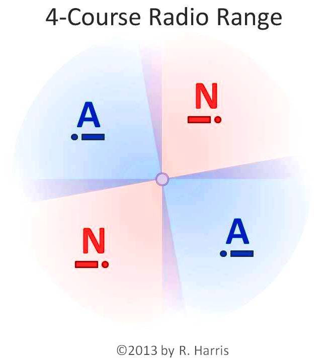
electricity. LF/MF 4-COURSE RADIO
RANGE By the mid-1930s,
the U.S. government established a network of aerial navigation radio towers
across the nation, along well-traveled air routes -- "airways" --
with the transmitter and their antennas so arranged as to project a
"beam" with a constant tone, audible on the radio when the pilot was
on course -- "on the beam." When off to one side or another,
different sounds would be heard. This system --
the "four-course radio range" (so named because each station radiated
four beams) -- worked well for aircraft on specific narrow air routes, during
mild weather, and more or less tolerably during lightning storms (though, being
an LF/MF range, the lightning static noise was a common nuisance, often painful
to pilots' ears). The system suffered other problems as well -- including a seriously disorienting vagueness and ambiguity in signals, which required some careful thinking and interpretation while using the system -- not too difficult in fair weather, but challenging when flying at night, or on instruments, especially in rough weather.
(For more on on the four-course radio range,
click here
for a brief illustrated tutorial.)
AUTOPILOT In the 1940s,
World War II caused a rapid growth in avionics development. The first
widely-used "automatic pilot" ("autopilot") was a system
that monitored certain instruments and adjusted the position of the pilot's
flight controls to keep the airplane upright and flying on a specific heading, and/or at a specified altitude;
more advanced autopilots were developed to allow the plane to automatically
track a radio beam, remaining pointed towards the radio signal. RADAR During World War
II, British and American forces invented a system of high-powered, narrow-beam
radio transmissions that could travel dozens or hundreds of miles, and reflect
off of metal objects (including buildings, ships and planes), with the return
signal being detected by a special antenna, and the distance measured by an
electronic instrument that indicated how long the signal took to return to the
station, when transmitted in a given direction. The concept was called
"Radio Detection And Ranging" ("RADAR") Radar was
quickly developed into a sophisticated instrument that could portray the
relative direction and distance to an object by television-like display. Powerful aircraft-detecting radar
was useful for both mililtary aircraft and ground-based air-traffic controllers (and
air-defense systems).
An additional value for radar was in detecting the
presence of rain or other precipitation, surface water, and obstacles, at a distance, allowing safe
navigation around (or through) bad weather, even in darkness. The ability of
the radar to detect and display the outlines of bodies of water and
obstacle-filled cities improved navigation, as well. This worked even on low-powered radar carried in civilian aircraft, which, however, could not detect other aircraft. TRANSPONDER
& IFF During wartime,
it was important to know if the aircraft you were seeing on radar were friend
or foe. The solution was to develop a radio ("transponder") that
detected the signal from a radar, and responded by transmitting a coded signal
that could trigger a different kind of display on radar. The pilot could
"dial in" a secret code number, and the transponder would send that
signal in reply whenever "interrogated" by a radar signal. The device
became known as "IFF" -- "Identification: Friend or Foe."
In peacetime, the same transponder technology proved useful in assisting air
traffic controllers in differentiating between multiple targets on a radar
scope, and transponders became required equipment -- first on airliners, then,
increasingly, on smaller and smaller craft. RADAR
ALTIMETER (RADIO
ALTIMETER) Applying the
lessons from radar, the aviation industry developed a very short-range,
low-powered radar, pointed down from the aircraft towards the ground, to
precisely measure the plane's altitude above the ground. This "radar
altimeter," along with regular radar, provided the first "terrain
avoidance system" for blind flying. Radar altimeters also provided
precision guidance during takeoff and landing. VHF RADIO By the 1950s,
frustrations with LF/MF radios -- both communications and navigation -- led to
a shift towards static-free VHF (very high frequency) radios (just above the
frequency range of commercial FM broadcast radio), which were far less
susceptible to lightning and other interference.
At this time, early VHF radios served as both communication and navigation radios, with both communications transmitter/reciever ("COM transciever") and navigation reciever ("NAV" reciever) contained in the same unit. This combination radio unit became known as a "NAV/COM," and the term -- and concept -- remains common to the present.
Early low-cost VHF COM transcievers often were very limited in the number of individual frequencies ("channels") on which they could transmit. While simple continuous analog tuning (similar to a cheap portable AM/FM radio) was adequate for the COM receiver, the COM transmitter was legally required to operate with extreme precision, on exactly the right frequency, to prevent interference with others on adjacent channels; this required the use of crystals to provide exact frequency tuning for the transmitter.
With crystal-controlled transmitting, a pilot could tune his continuous analog tuner to the same frequency as his transmitter by keying his microphone (or setting a button on the radio) while tuning the receiver. When he heard a whistling sound, his receiver was tuned to the same exact frequency as his transmitter. This technique was known as "whistle-stop" tuning.
More sophisticated NAV/COM units contained crystals for both the transmitter and reciever, and used a frequency selector knob that tuned both simultaneously. By the 1960s, nearly all VHF NAV/COM radios operated this way, with some accommodating up to 360 channels.
By the late 1970s, a new electronic technology -- "phase-locked loop" -- became available, allowing the VHF COM radios to be tuned to any of hundreds of frequencies with only a handful of crystals, or none at all, sharply reducing the cost of multi-channel NAV/COM radios, and making it practical to further divide the aviation radio band into more channels -- 720 channels in all -- reducing confusion in densely populated areas by reducing the number of airports using the same radio channels.
VOR - VHF
OMNI-RANGE While the old
four-course radio ranges worked well for navigating aircraft on specific narrow air
routes, during mild weather, and more or less tolerably during lightning
storms, the switch of navigation radios to static-free VHF frequencies was also
accompanied by a more sophisticated and versatile direction-finding system:
the VHF Omni-directional (Radio) Range ("VOR"). VOR
transmitters transmitted signals that allowed the VOR receiver in the airplane
to know the precise directions to (and from) the station, in any weather. A
very slightly different signal was sent out on each of 360 different
"radials" (one for each degree of the compass). The VOR receiver
could determine which radial the plane was on -- what direction the plane was
from the station -- by the precise signal it received from the VOR. The new VOR
indicators in the cockpit presented a slightly different appearance from the
traditional ADF compass dial. By comparison, the VOR indicator allowed the
pilot to "dial in" a specific desired direction to (or from) the
station, and a needle (if centered) would tell him he was on that
"radial", and (if not centered) how many degrees the airplane was
right or left of the desired radial. With this
system, a single station could transmit "radial" beams for more than
just four airways -- as many as a dozen airways could easily converge on a
single station (and, theoretically, up to 360 -- the number of degrees in a
full circle around the station). This made possible more airways, connecting
more airports and communities with safe instrument-flight guidance. ILS -
INSTRUMENT LANDING SYSTEMS (including: Marker
Beacons, LOC-
Localizer, & GS - Glide
Slope) While the
directional guidance available from radio ranges and beacons was useful
enroute, a miniature (low-powered) version of these ranges was needed for
precise local flight guidance at an airport, particularly to guide pilots
precisely to the end of a runway in "blind flying" conditions, and enable
the pilot to line the aircraft up with the runway. Early
"blind landing" systems were mostly just simple radio beacons --
"Marker Beacons" -- placed along a route towards the end of a runway.
Typically, there were two or three beacons (Outer Marker, Middle Marker, Inner
Marker). Typically,
using a DF or ADF, the pilot flew to the Outer marker, then steered his plane
to a course matching the runway alignment. As the pilot slowed down and
descended for landing, he listened in his headphones for the beeping of the
Middle Marker and Inner Marker, to gauge his progress and position on final
approach. Getting the
pilot "lined up" exactly on the runway, though, required something
more. For precise local guidance, the airports installed UHF (ultra high
frequency) "Localizer" ("LOC") beacons projecting a beam
precisely along the centerline of a runway. An indicator on the pilot's panel
(typically the VOR indicator, doing double-duty), would show whether the pilot
was lined up correctly, or how many degrees left or right of the runway
centerline the airplane was. However, owing
to obstacles and runway characteristics, some airport approach paths required
more than horizontal guidance by the localizer -- vertical guidance on the
exact angle of descent (glide slope) was needed. Accordingly, "glide
slope" ("GS") system emerged, using horizontal UHF beams to
enable the pilot's VOR indicator (when equipped with an extra horizontal
needle) to let the pilot know if he was "on the glideslope" or above
or below (and by how many degrees). Today, most ILS
systems incorporate one or more of these features: Outer Marker beacon, Middle
Marker beacon, Localizer, and/or Glideslope. In modern times, MLS
("microwave landing system") and other ILS techniques have been
developed, including variations on GPS systems (see "GPS" below), but
VOR-related ILS systems remain widespread. DME - Distance
Measuring Equipment
One frustration
with radio ranges and beacons was that direction-finding avionics could tell
you which DIRECTION they were, but not how far. The military
led the way to solving this issue with the "Tactical Air Navigation"
system ("TACAN") -- an enhanced version of the VOR, but operating at
UHF (ultra-high frequency). Other than the
higher (military) frequency, the key difference of TACAN was the addition of a
special kind of transponder, in which the aircraft transmitter sent a momentary
pulse out (in all directions), and waited to hear a corresponding reply signal
from the TACAN. By precisely measuring the delay (just a microscopic fraction
of a second), the airplane's TACAN receiver could calculate the distance to the
station. Two or more
distance measurements, compared to an internal clock in the TACAN receiver, indicated
the speed of the aircraft towards (or away from) the VORTAC or VOR-DME. A
simple switch on the TACAN receiver enabled an indication of speed rather than
distance. TACAN's
distance-and-speed measuring features were so attractive that a version
("DME" -- distance-measuring equipment) was integrated into many civilian
VOR stations on the ground, which then became known as VORTAC or VOR-DME
stations. RNAV - Area
Navigation While the VOR was
a solid advance over the LF/MF beacons and radio ranges, it still limited
pilots to navigating along specific radials between stations. To achieve
"free flight", a new system called "RNAV" -- Area
Navigation -- was developed and promoted in the 1970s. RNAV is
essentially a navigation computer, in the airplane, that automatically
calculates the precise position of the airplane based upon direction and
distance to a VORTAC or VOR-DME, using information from the plane's VOR and DME
receivers. Once the position of the plane is calculated, the pilot can program
the RNAV computer to create a "waypoint" anywhere within the reach of
the station and direct the RNAV computer to treat that waypoint as an imaginary
VOR station, triggering the VOR indicator to operate as if it was receiving a
signal from a station at that waypoint.
With this pilot-programmable
"waypoint" system, RNAV computers allow pilots to create their own
"airways", and fly on them, without being confined to official
airways, flying to-and-from the locations of real VOR stations. This concept
was promoted as "free flight" (though not the only meaning of that
term). INS - Inertial
Navigation System Aircraft
operating over vast stretches of ocean, and military aircraft operating over
large areas of hostile territory, were often deprived of radio navigation
aids. An exotic system of instruments -- using gyroscopes and accelerometers
that sensed the movement of the plane by effects on their inertia,
and tracking changes over time with a precise clock -- physically
measured an airplane's position and movement relative to a fixed point of
origin. The INS indicated precise latitude and longitude coordinates to the
pilot throughout the flight.
INS systems, at their most precise, were used to
guide bombers to distant targets around the globe, without any reference to
external radio signals. Due to the exotic nature of their high-precision
electronic and mechanical instrumentation, INS systems were extremely
expensive, and normally limited to military and commercial aircraft, and
high-end business jets. LORAN -
Long-Range Navigation LORAN --
"Long-Range Navigation" -- was originally developed to guide ships
and submarines at sea. Using VLF (very low frequency) radio signals, which
have extremely long range even with relatively little power, LORAN stations
transmitted a complex varying range of signals that overlapped signals from
other LORAN stations. By knowing the geographic locations (latitude and
longitude coordinates) of two or more LORAN stations, a LORAN reciever tuned to
them could compute the (fairly precise) location of the aircraft.
While not as
useful over land as the other forms of navigation, LORAN's extraordinary range
made it useful over water, and other vast, unpopulated areas. With the
development of more modern LORAN instruments, the system became popular even
for light aircraft use over land. Around the turn of the century, with the
rise of GPS (see below) LORAN became largely obsolete, and was generally
discontinued. MOVING MAPS The ideal cockpit
instrument for navigation has always been a "moving map" that would
always display the pilot's exact position on a map that moved as the aircraft
moved. In practice, this has been impractical until fairly recently, for a
number of reasons. But as early as the 1950s, moving map systems became a
concept that grew into limited practical use by the 1980s. The first
"moving maps" were just that: small paper maps that physically moved
on a set of rollers, on a panel in the cockpit. Timed to the speed of the
plane, and pre-oriented by the pilot along the route of flight, these primitive
moving maps were, at first, somewhat unreliable in presenting the pilot's exact
position. Eventually,
the technology evolved to TV screens showing recorded map images, which
adjusted their display based on the aircraft's exact position and speed, as indicated
by navigation signals from the other avionics. The development of DME, RNAV,
INS and LORAN made true precision moving-map systems possible and reliable. The rise of digital electronics with the "computer revolution" of the
1970s and 1980s made them far more practical and versatile. ----------------------------- NEXT
MONTH: Part
II: THE LATEST AVIONICS: ·
Automatic & Precision
Navigation: o
HSI o
Flight Director o
FMS o
GPS & WAAS ·
Aircraft/Ground Collision Avoidance: o
CAS/TCAS/PWI o
GPWS/EGGPWS/TAWS ·
Position &
Identity Reporting o
Mode C o
Mode S o
ADS-B ·
Integration &
Display: o
"glass
cockpits" ----------------------------- Author Richard Harris is
an FAA-certified aeronautics instructor who has developed and edited pilot
training manuals and official operating manuals for a wide range of aircraft,
from single-engine propeller aircraft to multi-engine business jets. He is an FCC-certified
radio technician and certified computer instructor, with occupational experience
as an aircraft instrument technician.
•
from battery power to generated current,
•
from vacuum tubes to transistors to integrated circuits,
•
from low frequencies to increasingly higher frequencies,
•
from mechanical displays to video displays,
•
from analog to digital,
•
from standalone units to integrated systems,
•
from simple-and-basic to complex-and-sophisticated.
Avionics prices, too, have fallen like the rest of the electronics world, but not at the same rate. Avonics remain among the costliest of all the world's electronics.
& TACAN -
Tactical Air Navigation