LF/MF Four-Course Radio Ranges
Text & Drawings Copyright 2013, 2014, 2025
by Richard Harris
DRAFT COPY 5H
Not for Publication
CAUTION:
DO NOT USE FOR PILOT INSTRUCTION
OR
SAFETY DECISIONS.
THIS INFORMATION HAS NOT BEEN VERIFIED.
LF/MF RADIO RANGES
 Throughout the 1920s, commercial aviation was hampered by the need to fly only in fair weather, when aircraft could navigate by visual references on the ground (a technique called "pilotage"), or by risky assumptions based upon compass, airspeed and clock indications, and reported winds — combined, calculated and plotted on a map (a technique called "dead reckoning"). Radio navigation technology emerged by the late 1920s, allowing fairly precise navigation without reference to the ground, nor the optimistic and daring trust in dead reckoning.
Initial efforts focused on simple radio beacons, broadcasting a simple Morse Code signal that could be "homed in on" using direction-finding ("DF") antennas. But these were of limited usefulness, and required pilots to have DF equipment, and know how to use it correctly. A simpler, clearer system was desired to ensure easy guidance for all aircraft — commercial, military and general aviation — using only a basic radio receiver.
By the mid-1930s, the U.S. government established a network of aerial navigation radio towers across the nation, along well-traveled air routes — "airways." (Map below shows extent of system by the 1950s; click to enlarge.) A clever system was devised that allowed a pilot to navigate fairly precisely along a narrow "beam," using only a basic radio receiver to listen to simple sounds — through a speaker or headphones — for location and guidance clues.
In addition to the beams, these early air-navigation radio stations also broadcast a wider set of signals that ensured reception and guidance from any location around the radio station — not just "on the beam." Because the entire range around the station was affected, these stations became known as "radio ranges."
The system used LF/MF (Low-Frequency / Medium-Frequency) radio frequencies — between 200 and 410 kHz — with some military radio ranges operating at as high as 536 kHz (just below the commercial AM broadcast band). This gave the system the name "LF/MF radio range" or simply "Low Frequency Range" (LFR).*
-
* The latter "LFR" term was technically incomplete, as some ranges operated above 300 kHz, and thus were technically "Medium Frequency" (MF) ranges (at the "lower end" of the 300–3,000 kHz, MF spectrum).
|
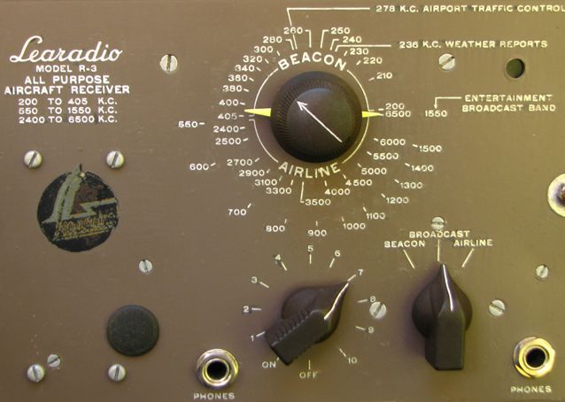
Shown below, a typical simple AM-type radio receiver for aircraft of the 1930s and 40s (this one developed by automobile-radio inventor Bill Lear, an avionics pioneer and later developer of the Learjet). The ON/OFF/volume knob is in bottom center. The 3-position band selector switch is in the lower right. Depending upon that switch's position ("BEACON," "BROADCAST," or "AIRLINE"), the large tuning knob (top center) selects a frequency from one of the these three radio bands. (The frequencies are calibrated in "K.C.": "kilocycles per second," same as kHz: kiloHertz). The "BEACON" band was home to the LF/MF beacons, including the 4-course radio ranges. This particular radio could receive the civilian beacons transmitting on frequencies between 200 and 405 "KC" (kHz), but not the military beacons between 410 and 536 kHz. It could also tune in the commerical AM "BROADCAST" band (550–1550 kHz), and the old "AIRLINE" communications band (2400–6500 kHz), |
|
On the LF/MF frequencies, with the then-current technology, pilots could use a four-course range with only a cheap, simple radio receiver — making this one of the least expensive radio navigation aids (for the airplane owner).Ā The underlying transmitter technology, too, was cheap and simple, and — due to the low frequencies — used very little energy to transmit an audible signal for dozens or hundreds of miles.
HOW IT WORKED
The LF/MF radio range transmitters (and their
antennas) were arranged so as to project four "beams," each with a constant
tone, audible on the radio when the pilot was on-course — "on the
beam."Ā(see purple beams in map-view diagram at right).Ā The beams were typically about 3–4 degrees wide. When the airplane was off-course — "off the beam," to one side or another — different sounds would be heard.
 To be exact, the
off-course signals were beeping Morse Code tones for the letters
To be exact, the
off-course signals were beeping Morse Code tones for the letters
"A"
(dot-dash, or
"bip-beep"),
and
"N"
(dash-dot or
"beep-bip").
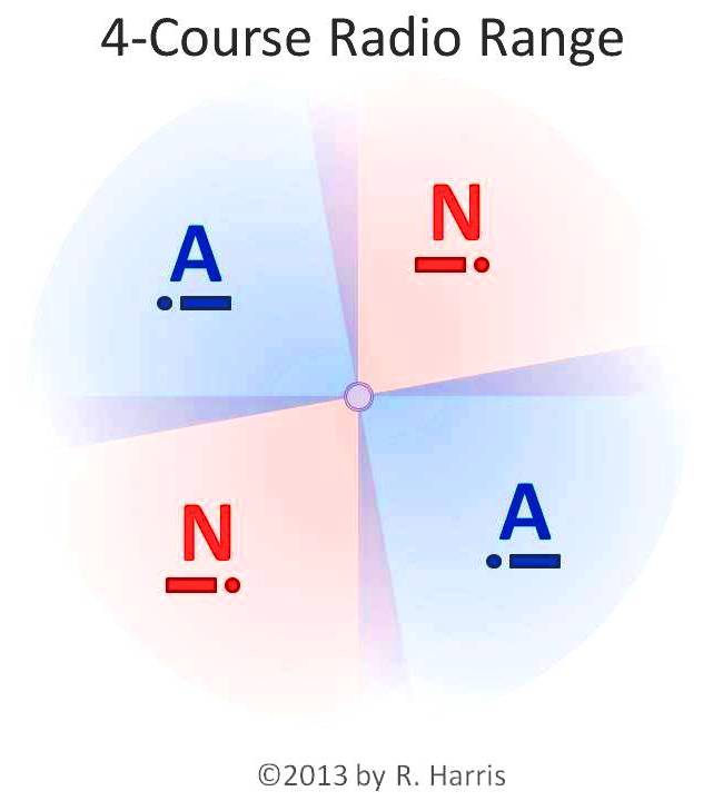
These "A" and "N" signals (which gave the radio ranges the common nickname "A-N ranges") were transmitted into slightly overlapping quadrants, around the station (see signal table, above-right, and map-view diagram, below-right).Ā
At the narrow zones where an A quadrant and an N quadrant overlapped, their bips and beeps merged into a continuous tone.Ā This narrow zone was known as "the beam," and was often aligned along a particular airway.
Pilots would tune their radio to the frequency of the desired radio range, and confirm that they had the right one tuned in by listening for an intermittent identifier signal — typically 3 letters (broadcast in Morse Code), often resembling an abbreviation of the name of the nearest town or airport — "DEN" (for Denver), "LUK" (for Cincinnati's Lunken Airport), and so on.
Once correctly tuned in, the pilot listened to the continuous signal from the station — which would be the Morse Code signal for "A" or "N" — depending upon which quadrant he was flying in — or a constant hum resulting from the overlapping "A" and "N" signals along the "beam" between two quadrants.Ā
Typically, the pilot's goal was to be "on the beam," following the centerline of an airway. But the ranges also helped off-airway navigation as well, by providing pilots with approximate location information, simply and cheaply.
|
LF/MF 4-COURSE RANGES as shown
on an AERONAUTICAL CHART (MAP) |
|
|
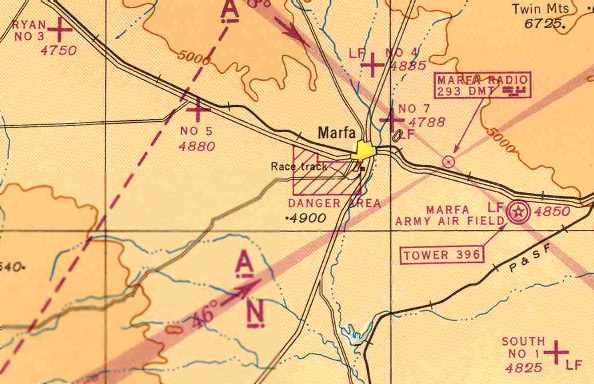
ABOVE:
A classic, basic depiction of a four-course range, showing the "beams" as four magenta rays emanating like a giant "X" from the station in the upper right portion of this map. In the center of the southwest beam, an arrow pointing to the station is labeled "46°," indicating the magnetic bearing to the station along the centerline of the beam. The letters "A" and "N," with their Morse Code signal equivalents, are shown on appropriate sides of each beam. The data block above the station indicates the station's frequency (293 kHz), and its intermittent identifier signal (in this case, the three letters "DMT" - for "Ft. Davis / Marfa Army Air Field, Texas," with the equivalent Morse Code signals).
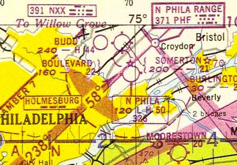
BELOW, RIGHT: A more complex display, showing the southeast beam from a four-course range near Albany, NY, projecting through the centerline of an airway, passing over Troy, 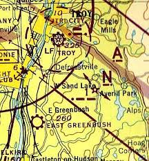 NY airport (and its local homing beacon). Notice the purple boundary lines of the airway on either side of the beam. Below the letter "N," on the south side of the beam, you can see a small magenta star with arrows pointing along the airway in both directions.
This represents the forerunner to the radio ranges: airway light beacons, projecting a beam in each direction along the airway, to provide night guidance before the radio ranges existed. The numeral "1," and the equivalent Morse Code signal, indicates the signal flashed repeatedly by the beacon, for identification distinguishing it from others on the route. These beacons continued in use for some time, along with the radio ranges — each supporting the other in clarifying a pilot's position.
NY airport (and its local homing beacon). Notice the purple boundary lines of the airway on either side of the beam. Below the letter "N," on the south side of the beam, you can see a small magenta star with arrows pointing along the airway in both directions.
This represents the forerunner to the radio ranges: airway light beacons, projecting a beam in each direction along the airway, to provide night guidance before the radio ranges existed. The numeral "1," and the equivalent Morse Code signal, indicates the signal flashed repeatedly by the beacon, for identification distinguishing it from others on the route. These beacons continued in use for some time, along with the radio ranges — each supporting the other in clarifying a pilot's position.
|
its pros and cons:
ADVANTAGES:
- Aural only: Any LF/MF radio receiver adequate.
(thus very affordable for Consumer)
- LF/MF
technology & (high) range/power ratio.
(thus very low-cost for Provider)
- Can carry additional audible info:
- identification (Morse Code)
- voice ID & info (including verbal weather reports)
- identification (Morse Code)
DISADVANTAGES:
- Ambiguity:
- no precise,
certain location (nor even line of position) indicated,
ĀĀĀĀĀ (except with DF/ADF) - 4 aurally-identical "beams"
- aurally-identical,
twin-but-opposite
A-quadrants and N-quadrants - DF/ADF or other range required for greater clarity
- LF/MF technology limits:
- lightning &
static interference
- interference from other LF/MF stations (especially when the pilot is using low-quality analog receivers)
- terrain/obstacle reflection (e.g.: off of mountains, large buildings)
- coastal "bending" (signals curving along coastlines)
- distant-station interference, especially at night, due to ionospheric reflection ("skip").
MYSTERIES & SOLUTIONS:
Shown in the drawings is a typical four-course radio range (though many were not so neatly symmetrical). Also shown is a typical airway (in this case, Airway "Green 7"), to which the radio range's west and east beams are aligned.
In the illustration at right, below, shown are four airplanes intending to acquire and follow the western
beam along the airway TO the station, cross over the station, and then fly the eastern beam FROM the station
to another destination.
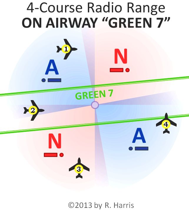
Airplane 1 is off-course, to the left of intended
course (the western beam), and thus in the northwest "A" quadrant,
hearing "bip-BEEP" (dot-dash) signal.
If Airplane 1 continues on present
course,Ā it will eventually cross the north beam, and the pilot will hear a continuous
"hum," as he crosses that beam.Ā After crossing that beam, he will
hear the "BEEP-bip" (dash-dot) sound of the northeast
"N"-quadrant.
Airplane 2, tracking along the center of Airway "Green 7", is ON-course to the station — "on the beam" — so pilot hears the continuous "hum" created by the overlapping signals of the northwest "bip-BEEP" (dot-dash) sound of the "A"-quadrant (to his left), and the "BEEP-bip" of the southwest "N"-quadrant (to his right).
If Airplane 2 continues on his current course, he will hear the hum constantly all the way to the station, then a brief silence in the "null zone" (or "cone of silence") immediately above the station, followed by the resumption of the hum as he flies on into the east beam on the other side of the station.
Airplane 3 is far off-course from the west beam, many miles to the south, in the southwest "N"-quadrant (and hearing the "N"-quadrant's "BEEP-bip" — dash-dot signal). But he's heading north, towards the west beam.
Airplane 4 is far off-course from the east beam, to the south, in the southeast "A"-quadrant (and hearing the "A"-quadrant's "bip-BEEP" — dot-dash signal). But he's heading north, towards the east beam.
Airplanes 1 and 4 — traveling at the
same groundspeed in this example — illustrate a classic example of the
ambiguity of the 4-course range.Ā Both airplanes are tuned to the same radio
range, and — despite being in completely different locations, relative to the
station, on completely different courses — hear exactly the same signals on
their radio.
As they each continue on their current (and different) courses,
each will hear the same changes in signal, at the same rate — despite their
completely different positions and courses.
Because of this ambiguity, it was important for pilots to have additional navigation cues.Ā While visual navigation helped in fair weather (and expert dead-reckoning helped in all conditions), pilots in the clouds really needed other instrument indications.
Five solutions existed at the time:
1.) Compare the change in radio range signals to the aircraft compass heading indication, and see which approximate course is likely, given the current heading and radio range signals.Ā This would make it easier for Airplanes 1 and 4 to know where they actually are, and are going (especially when they cross one of the beams).Ā This solution isn't perfect, and does not provide pinpoint precision location information, but does improve the pilot's evaluation of his probable approximate location and course.
2.)Ā Turn the aircraft until its fixed antenna was aligned with the station's direction.Ā
Many older aircraft, and light aircraft, had simple straight-wire, or fixed-loop, antennas that were directional in their sensitivity, but in a fixed positon on the aircraft. Turning the aircraft until the radio station signal faded out due to the antenna's angle (a narrow heading range, known as the "null zone") could point the way, as well.
For airplanes with an antenna aligned along the aircraft's longitudinal axis (nose-to-tail), the null zone was straight ahead and straight behind, so a when a pilot heard the station signal suddenly fade during a turn, he was — at that moment — on a heading directly to or from that station.
3.)Ā Use of DF/ADF instruments (see other article) could indicate the aircraft's precise direction to or from the radio-range station — a "line of position" relative to the station — though some early models did not necessarily indicate whether that direction was TO or FROM the station.
 4.)Ā DF/ADF
instruments could "triangulate" the aircraft's EXACT
position, by determining TWO lines of position relative to TWO different radio
stations — with the
airplane located at the point on the map where the two lines, passing through
the radio stations at the indicated directions, intersected.
4.)Ā DF/ADF
instruments could "triangulate" the aircraft's EXACT
position, by determining TWO lines of position relative to TWO different radio
stations — with the
airplane located at the point on the map where the two lines, passing through
the radio stations at the indicated directions, intersected.
A dual-needle ADF indicator (right), simultaneously monitoring two separate ADF radios, could show both lines of position at the same time, clarifying where the pilot was between them. A single-needle ADF indicator and radio were enough, if used as a 2-needle indicator by manually alternating the radio tuning between two different stations.
Both of these last two solutions required DF or ADF equipment.Ā Some smaller craft only had simple radio receivers, without DF/ADF capability.Ā
5.)Ā Listen to OTHER 4-course ranges, as well. Ā
Each range operated on its own locally unique frequency.Ā So other A-and-N signals, and beam hums, from other stations, could be heard by tuning in other radio ranges.
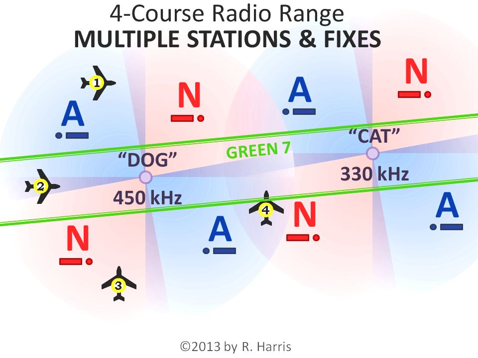 In the example
shown, with the first radio range "DOG" to the west, and an
additional radio range "CAT" shown to the east (and audible on
another frequency), the pilots of Airplanes 1 and 4Ā would have a much clearer
picture of their positions.
In the example
shown, with the first radio range "DOG" to the west, and an
additional radio range "CAT" shown to the east (and audible on
another frequency), the pilots of Airplanes 1 and 4Ā would have a much clearer
picture of their positions.
As Airplane 1
continued on an easterly course across the north beam of "DOG" — and into DOG's northeast
"N" quadrant — the "A" signal from CAT's northwest quadrant would continue to be audible, with increasing strength, indicating motion toward "CAT."
As Airplane 4 progressed on its northerly course, it would soon hear the hum of beams fromĀ
both "DOG" and "CAT," indicating it was crossing the
east-west airway.
Then, if it continued to fly north, it would fly north of the airway, and would then hear an "N" from
"DOG" and an "A" from "CAT," further clarifying
the airplane's location.
|
|
|
|
Many areas (especially densely populated regions) were covered by multiple overlapping radio ranges, allowing fairly good position-fixing.Ā
While flying along a beam that marked an airway, a pilot could get some indication of his position and groundspeed by noting the times of station passage (indicated by a brief period of signal loss in the "null zone" above the station antennas), and the times that he passed the intersecting beams from other nearby radio ranges, while on the airway.
FADING INTO HISTORY
While imperfect, the four-course ranges were an ingeniously simple and practical system for fairly precise navigation along airways, and radically improved air navigation safety in aviation's "Golden Age" between the World Wars, and well into the mid-20th Century.ĀĀ These ranges, coupled with the various supporting light and radio beacons, made it possible for relatively safe day-and-night, all-weather flying, which revolutionized the reliability and practicality of commercial airlines — both passenger and air cargo operations — as well as greatly increasing the capabilities and responsiveness of military and general aviation.
In the United States, with the coming of the VOR (see other article), the four-course ranges were phased out almost completely by the mid-1960s. The static-free, needle-wiggling VOR — VHF Omni-directional Radio ranges — brought much greater precision, reliability and versatility to air navigation, but largely were arranged in the locations, and with the names, of the four-course ranges that preceded them.
A few LF/MF ranges were retained in Alaska, where vast spaces and mountain ranges required plentiful cheap radio navigation aids, capable of bending over mountains, rather than being blocked by them (as happens with VHF and higher-frequency signals).Ā Many other nations retained them for decades longer, as a matter of economics and/or terrain, especially in remote or mountainous regions.
Today, the four-course ranges are extinct throughout the world, having been largely replaced by subsequent
technologies — chiefly VOR, TACAN, LORAN and GPS — most of which are now available at
relatively low cost, with much greater precision than the LF/MF radio ranges
once provided.
The once-popular expression "on the beam" — a phrase that once diffused throughout the general public, signifying being "on-course," "on the right track", "making good progress," or simply "acting correctly" — has begun to fade from the English language. Today, only a handful of old-timers know the original meaning — and the challenges and rewards — of that once all-important goal.
~RH
For a dyanmic World War II training film on the topic, see:
1941 U_S_ ARMY AIR CORPS TRAINING FILM
RADIO AIDS TO NAVIGATION 32084
-on YouTube.com